Friday, September 30, 2016

Creating a local Esxi user/role using PowerCLI

Steps Involved:

1. Connect to the Esxi Host:

Connect-VIServer -Protocol https -Server FQDN_or_IP_of_VMhost -User root -Password  your_password

2. Add a local user with the New-VMHostAccount command:

New-VMHostAccount -Id account_name -Password your_new_password -Description description_of_the_user

3. Add a new role and specify the privileges involved:

New-VIRole -Name your_role_name -Privilege “eg: Settings”

4. Bind the new role to the new user:

New-VIPermission -Entity FQDN_or_IP_of_VMhost -Principal account_name-Role your_role_name -Propagate:$true

Thursday, September 29, 2016

Virtual SAN Acronyms

  • Virtual SAN related Acronyms:

  • CMMDS – Cluster Monitoring, Membership, and Directory Service

  • CLOMD – Cluster Level Object Manager Daemon

  • OSFSD – Object Storage File System Daemon

  • CLOM – Cluster Level Object Manager

  • OSFS – Object Storage File System

  • RDT – Reliable Datagram Transport

  • VSANVP – Virtual SAN Vendor Provider

  • SPBM – Storage Policy-Based Management

  • UUID – Universally unique identifier

  • SSD – Solid-State Drive

  • MD – Magnetic disk

  • RVC – Ruby vSphere Console

Storage providers fail to auto-register for certain Virtual SAN hosts (2109894)

Details

When you move a Virtual SAN host to a Virtual SAN cluster on another vCenter Server, you see this message: 

The Virtual SAN host cannot be moved to the destination cluster: Virtual SAN cluster UUD MisMatch: (Host: <UUID>, destination: <UUID>)

Solution

Typically, storage providers for Virtual SAN hosts are automatically registered. However, when you move Virtual SAN hosts to a Virtual SAN cluster on another vCenter Server, the storage providers might fail to auto-register for Virtual SAN hosts. As a result, you see the error message. 

After you move Virtual SAN hosts to a Virtual SAN cluster on another vCenter Server, update the storage providers that are registered for the hosts.
 
To update the storage providers:
  1. Browse to vCenter Server in the vSphere Web Client navigator. 
  2. In the Manage tab, click Storage Providers.
All hosts that have a storage provider for Virtual SAN appear on the list.

If a storage provider for the selected host is not listed, perform these steps:
  1. Browse to the Virtual SAN cluster in the vSphere Web Client navigator.
  2. On the Manage tab, click Storage Providers.
  3. Click the Synchronize all Virtual SAN Storage Providers with the current state of the environment icon. 
This registers Virtual SAN storage providers for all the hosts.

If no registered storage provider is found for the selected Virtual SAN hosts, you cannot create a new VM storage policy or configure the existing policies

Understanding Virtual SAN on-disk format versions (2145267)


Purpose


This article outlines all Virtual SAN on-disk format versions, their purposes, and alternate version numbers where applicable.
Virtual SAN (VSAN) has several different on-disk format versions available depending on the version and upgrade history of the cluster. Some on-disk format versions are transient while some are intended for long-term production.

Important: There can be some deviation between the on-disk format version displayed in the vSphere Web Client and the version displayed during command-line troubleshooting or reporting.

Resolution


VSAN 6.2 hybrid disk group performance degradation (2146267)


Symptoms

  • After upgrading a Virtual SAN (VSAN) environment with Hybrid disk groups to version 6.2, some virtual machines resident on VSAN datastores may exhibit poor disk IO performance compared to previous versions of VSAN.

    For example, Virtual Machine Read and/or Write IOs may have poor response time than on Virtual SAN 6.1 or Virtual SAN 6.0.
  • A significantly lower than expected read cache hit ratio is observed on Virtual SAN caching tier.
  • A higher percentage of IOPS may be observed on capacity tier disks (Magnetic disks) on Hybrid diskgroups when compared to VSAN 6.0 or VSAN 6.1 systems.

Purpose

The VSAN 6.2 performance issue with hybrid disk groups is resolved in VMware ESXi 6.0 Patch Release ESXi600-201608001.

A hybrid disk group comprises of one Solid State Disks (SSD) for the cache tier and one or more Magnetic HDDs (MDs) for the Capacity tier.

Cause

In VSAN 6.2, new data services are introduced. One of these data services is Deduplication and Compression. Deduplication and Compression are not supported for Hybrid VSAN configurations. 

This issue is caused by VSAN 6.2 performing low level scanning for unique blocks, which is related to deduplication, can still occur on VSAN hybrid disk groups. This causes performance deterioration on Hybrid Disk groups, as it has a significant read caching performance impact on the SSD cache tier of VSAN disk groups.

Resolution

This issue affects VSAN 6.2 Hybrid deployments only. This issue is NOT applicable to All Flash VSAN Clusters.

This issue is resolved in VMware ESXi 6.0 Patch Release ESXi600-201608001 available at VMware Patch Downloads. For more information, see:


To work around this issue if you do not want to upgrade, VMware advises to turn off the dedup scanner option on each VSAN node contributing to a Virtual SAN Hybrid cluster.

Prerequisites:
  • A VSAN node must be placed in maintenance mode (with the Ensure Accessibility option) and a restart is required.
  • These commands must be run on each ESXi host in the VSAN cluster.
  • These commands result in persistent changes and remain configured across reboots.

To disable the dedup scanner:
  1. Connect to your ESXi VSAN cluster  node using the ESXi Shell.
  2. Run this command to turn off the dedup scanner:

    esxcfg-advcfg -s 0 /LSOM/lsomComponentDedupScanType
  3. Verify the new setting using this command:

    esxcfg-advcfg -g /LSOM/lsomComponentDedupScanType

    • For Hybrid VSAN deployments, the value of lsomComponentDedupScanType is 0 when disabled.
    • The default value for lsomComponentDedupScanType is 2.
  4. To apply the new setting on a Virtual SAN Cluster, select the Ensure Accessibility option and place each host in maintenance mode.
  5. Reboot each host or node in a rolling fashion to ensure Virtual VSAN objects remain available.

    Note: The requirement for a reboot is to ensure any active dedup scanning session of existing data will be terminated in a consistent manner across a given cluster.

How to add a host back to a VSAN cluster after an ESXi host rebuild (2059091)

To rejoin the ESXi host to the Virtual SAN cluster:

  1. Install the host, ensuring that you preserve the Virtual SAN disk partitions.
  2. Configure the Virtual SAN VMkernel port group on the host. For more information, see Configuring Virtual SAN VMkernel networking (2058368).
  3. Reconnect the host to the Virtual SAN cluster in vCenter Server.
  4. Connect to one of the remaining Virtual SAN cluster hosts using SSH.
  5. Identify the Virtual SAN Sub Cluster ID using this command:

    # esxcli vsan cluster get

    You see output similar to:

    Cluster Information
    Enabled: true
    Current Local Time: 2013-09-06T18:50:39Z
    Local Node UUID: 521b50a1-ad57-5028-ad51-90b11c3dd59a
    Local Node State: MASTER
    Local Node Health State: HEALTHY
    Sub-Cluster Master UUID: 521b50a1-ad57-5028-ad51-90b11c3dd59a
    Sub-Cluster Backup UUID: 52270091-d4c9-b9a0-377b-90b11c3dfe18
    Sub-Cluster UUID: 5230913c-15de-dda3-045e-f4d510a93f1c
    Sub-Cluster Membership Entry Revision: 1
    Sub-Cluster Member UUIDs: 521b50a1-ad57-5028-ad51-90b11c3dd59a, 52270091-d4c9-b9a0-377b-90b11c3dfe18
    Sub-Cluster Membership UUID: f3b22752-f055-bcc5-c622-90b11c3dd59a

  6. Run this command on the newly rebuilt ESXi host using the Sub Cluster UUID identified in step 5:

    # esxcli vsan cluster join -u sub_cluster_UUID

    For example:

    # esxcli vsan cluster join -u 5230913c-15de-dda3-045e-f4d510a93f1c
  7. Verify that the host is now a part of the Virtual SAN cluster by running the command:

    # esxcli vsan cluster get

    You see output similar to:

    Cluster Information
    Enabled: true
    Current Local Time: 2013-09-06T11:51:51Z
    Local Node UUID: 522756f5-336a-8de0-791a-90b11c3e1fb9
    Local Node State: AGENT
    Local Node Health State: HEALTHY
    Sub-Cluster Master UUID: 521b50a1-ad57-5028-ad51-90b11c3dd59a
    Sub-Cluster Backup UUID: 52270091-d4c9-b9a0-377b-90b11c3dfe18
    Sub-Cluster UUID: 5230913c-15de-dda3-045e-f4d510a93f1c
    Sub-Cluster Membership Entry Revision: 1
    Sub-Cluster Member UUIDs: 521b50a1-ad57-5028-ad51-90b11c3dd59a, 52270091-d4c9-b9a0-377b-90b11c3dfe18, 522756f5-336a-8de0-791a-90b11c3e1fb9
    Sub-Cluster Membership UUID: f3b22752-f055-bcc5-c622-90b11c3dd59a

  8. In the vCenter Server, refresh the Virtual SAN status view. All hosts now report the status as Healthy.

Wednesday, September 28, 2016

NSX Traceflow Utility

Understanding NSX's Traceflow Utility

What Traceflow is for:


Traceflow is useful in the following scenarios: 


Troubleshooting network failures to see the exact path that traffic takes 

Performance monitoring to see link utilization 

Network planning to see how a network will behave when it is in production 


Traceflow operations require communication among vCenter, NSX Manager, the NSX Controller cluster and the netcpa user world agents on the hosts.

For Traceflow to work as expected, make sure that the controller cluster is connected and in healthy state.


Step 1: 
Log into the Web Client and Select the NSX Plugin


Step 2: 
Select Traceflow on the left.


Step 3: 
Select the source vm.


Step 4: 
Select the vnic of that vm.


Step 5: 
Now select the destination.


Step 6:  
In this case, select Layer 3.


Step 7: 
Add the IP address of the source vm.


Step 8:  
Verify your selections and click on Trace.


Step 9: 
Wait a few seconds...


Step 10: 
In this case, notice the firewall dropped such traffic. The firewall demo is found on the previous post. 


Step 11:  
Same trace without the firewall rule preventing that type of traffic.


NSX Firewall Rules Demo

How to Add a Firewall Rule to NSX:

How DFW rules are enforced:
DFW rules are enforced in top-to-bottom ordering. Each packet is checked against the top rule in the rule table before moving down the subsequent rules in the table. The first rule in the table that matches the traffic parameters is enforced Because of this behavior, when writing DFW rules, it is always recommended to put the most granular policies at the top of the rule table. This is the best way to ensure they will be enforced before any other rule.

Step 1: 
Double click on the NSX plugin and select Firewall on the left side. Click on the Green Plus Sign to add a rule. Rules need a name, a service/s to accept or reject, a source and a destination. In this case, the rule is called "Reject Ping"


Step 2:  
Next, select the source. The source could be a cluster, a vm, a vnic, etc.


Step 3: 
Select the destination. In this case another vm is selected. 


Step 4:
Select the service to allow, block or reject.
 

Step 5:  
Select the action and direction. In this case, Reject and both in/out were selected.


Step 6: 
Once finished populating all the fields, don't forget to Publish the changes.
 

Step 7: 
Test the rule. Notice the ping from this vm is simply rejected by the firewall.


Tuesday, September 27, 2016

Deploying an NSX Manager 6.2.4, NSX Controllers, Logical Switches and Routers

Deploying an NSX Manager:

Part 1: Installation and configuration of the NSX Manager.

Step 1: 
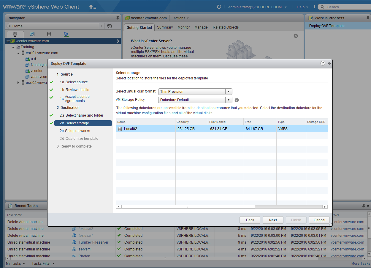
Download the .ova from vmware.com/downloads and deploy via ovf. The download is about 2.5 gbs in size.. The linux-based appliance uses 4 vcpus and 16gbs of ram. All of the ram is reserved by default. NSX relies on distributed switches, so read the installation guide to see how to configure those switches.


Step 2: 
Connect to the appliance via a browser and log in as admin. The password in this case is VMware1!VMware1!.


Step 3: 
Register the appliance with the vCenter Server. This is a one to one relationship.


Step 4: 
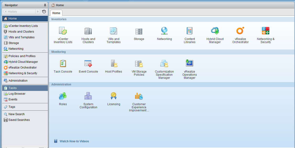
Log out and log into the vCenter Server. Notice the NSX Plugin


Part 2: Installation of the NSX Controllers.

Step 5:
After adding the NSX license, install 3 nsx controllers. Only one will be installed in this case. To do so, click on the NSX plugin, go to installation and click on the green plus sign. In the process, you will have to have a cluster in place and create an IP pool.


Step 6:
Install the NSX Modules for the esxi hosts. Click on the Host Preparation Tab and click on Actions.


Step 7:
Configure VXLAN on the esxi hosts.


Step 8:
Add the Segment ID Pool.


Step 9: 
Configure a Transport Zone.


Step 10:
Create a Logical Switch.


Final Note: Now migrate the vms to the logical switch and test connectivity.

Part 3:  Deploy a Distributed Logical Router

Step 1: 
On the left side, click on NSX Edges


Step 2:
Give it a name, select  a name and click on next.


Step 3: 
Give the main user (admin) a password and enable ssh (optional).


Step 4:
Click on the Green Plus Sign and specify the cluster name, the datasote and hostname. 


Step 5:
Connect the router to a port group in a distributed switch.


Step 6:
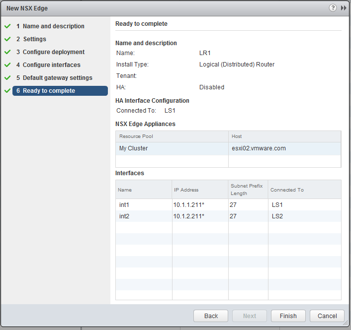
Provide the two ips for the internal interfaces that connect the two logical switches by clicking on the green plus sign. The two ips connect the 10.1.1 and 10.1.2 networks in this case.


Step 7: 
Click on the Green Plus Sign to add the ips of the two interfaces.


Step 8:
Add the two ips and verify the values and connectivity.


Step 9: 
Click on Finish.

 Step 10: 
After changing the gateways of the vms (to the ips of the router), test connectivity. In this case, linux1 resides on esxi02 and is connected to the second logical switch (10.1.2.201) is able to ping another vm located on esxi01, logical switch1 in the 10.1.1 network.